Horizon Sensor. 2007-08-02
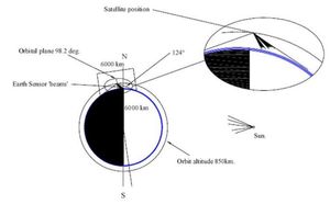
The Horizon Sensor is a dual unit with sensors for visible light and near infrared. It will be mounted on an X or Y face on the ‘attic’ that has been added to the satellite structure.
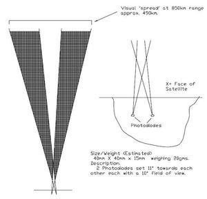
The sensor comprises two pairs of photodiodes set at an included angle of 22° such that each pair of light sensitive ‘beams’ converge and cross at a point a few cm from the face of the ‘attic’. Each beam has a 10° field of view. ( Fig 1) The ‘scan width’ of the combined beam at orbital altitude is 490kms. By virtue of this configuration, the only light source in the Universe big enough to illuminate both photocells at the same time is Sunlight reflected from the Earth’s surface.
The associated electronics will output a ‘high’ (+5V) as each cell (of the pair) is illuminated. The ‘highs’ will indicate earth pointing and the timing of the second high of the pair will occur as the second (trailing) cell crosses the horizon or the terminator (day/night line) depending on the attitude and movement of the satellite. As with the sun sensor readings, the instant triggering of each cell will be accurately timed and used as a component of the horizon / terminator detector for use with the positional algorithms.
The temporary (occasional) illumination of cells by any other celestial object will be detected, evaluated and rejected by the software. (The Moon and Sun will certainly trigger the photodiodes individually and that may be of interest for further experimentation but is not being considered for any ADAC ‘added value’ at this time.)
In general the angular level of accuracy of the horizon sensor is low providing a “ball park” indication of the position of the Earth. The level of service this ‘budget’ device will provide to the overall ADAC is more confirmatory value than of accurate reference. It will be interesting, however, to see just how accurate it can be made with some imaginative software. The Camera will tell! (See Camera)
Considerable work will be needed to interpret data from this sensing device as its illumination will depend on a number of factors:
1. The rotational speed and direction of the satellite
2. The orientation of the satellite whilst it is rotating.
For instance, if it’s rotating with its X-Y axis parallel (or nearly parallel) to the geomagnetic field (almost North/South) the photodiode ‘beams’ will be sweeping the horizon “sideways” and both diodes will illuminate together! This will not be a sought after orientation but it could happen when trying to achieve the objective of pointing the -Z face (the face of which is lies X-Y) at the Sun.
This is not a particular problem: the other sensors will supply the necessary outputs to provide computational data in this event. At worst, instantaneous or near instantaneous outputs from the horizon sensor outputs – ‘leading diode’ and ‘trailing diode’ - will provide some useable ‘orientation confirmation’ adding to the ADAC picture when input into the ADAC calculations.
3. The unknown effect that the gradual light reduction will have on switching as the sensor sweeps the terminator.
The sensing of light/dark when crossing the illuminated horizon (atmospheric cusp) is expected to be close to instantaneous due to the stark difference between the brightness of the Earth’s ‘edge’ and deep space. When crossing the terminator, however, the light level will gradually fade/increase and will at some point reduce to a level that will trip (off or on) the photo diodes.