Status 2023-06
KiwiSAT will not fly.
At its 2023 Annual General Meeting AMSAT-ZL unanimously voted to dissolve. We do not have the manpower, finances, or interest to conduct a successful launch campaign to get KiwiSAT to orbit.
The group is looking for a site where the satellite can be displayed.
Status 2017-07-02
KiwiSAT. All systems are now fight ready.
Outstanding:
Final integration - All hardware is complete and KiwiSAT is operational. Final integration to launch ready awaits addition of the flight batteries and fragile solar cells.
Launch negotiation - AMSAT-ZL are in discussion with several agencies. Funding is an important aspect as costs increase and resources are stretched.
Flight Software - Software is developing on three fronts:
-
Boot loader/Operating System
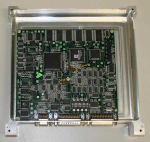
Clayton (ZL3TKA), well aided by a VNC connection between his QTH (in Canberra) and the clean area then in Massey University in Albany on the Auckland North Shore (See image), developed and wrote the boot loader. A period of intensive reliability testing has proved the reliability of this important link in KiwiSAT control.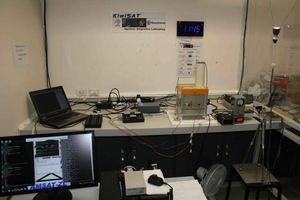
Two ROM development chips contain the code in flash form in sockets on the IHU Main Board. This will then be burnt onto non volatile memory IC’s and permanently mounted for flight operation. Pre-flight testing and calibration continue.
-
ADAC Application Software
Whilst not absolutely essential pre-launch, it is considered highly desirable to complete the (non-ADAC) operational software whilst the satellite is in the clean area and a small team have expressed an interest in a coordinated approach to this activity. Clayton will take the lead and when at least a basic (but totally reliable!) command system is proven, the launch sponsorship campaign will be ramped up to full gear.
AMSAT-ZL volunteer Dr Jon Henderson provided an active supervisory role on Massey University Masters student Kirill Makarov for this activity and progress is now excellent in this area. The NZART Radioscience Education Trust sponsored Kirill who breathed some greatly appreciated extra enthusiasm into the project. (See ADAC Status section for details) -
Ground Station Telemetry Decode Program
Terry (ZL2BAC) took on the development of the ground-station telemetry decode software and great progress has been made. The Telemetry update posted on this site provides the basic information and Terry is happy to communicate directly with those having particular interest in this aspect. See Telemetry page for more details.
Regulatory requirements - KiwiSAT is registered with the ITU in preparation for launch.
The Structure
From the bottom of KiwiSAT and working up.
Tray No 1
The Transmitter tray is completed to Flight Ready status. Now integrated into final assembly. System meets all expectations.
Tray No 2.
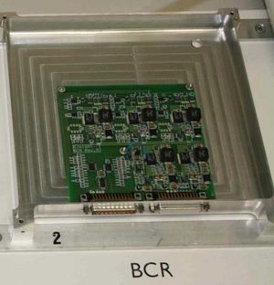
The BCR (Battery Charge Regulator) is completed and integrated into final assembly system. Currently active in controlling power from Solar cell simulators to the fully integrated KiwiSAT unit.
Tray No 3.
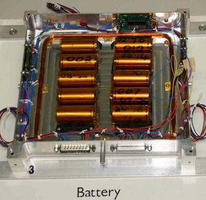
The battery tray. While this tray is completed and ready for flight. A spare set of batteries are being used during the bench testing.
Tray No 4.
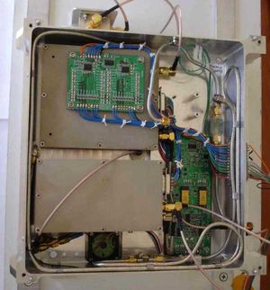
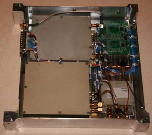
The IHU and RAM disk
The IHU (or Integrated Housekeeping Unit) is the essential
central satellite system control computer.
This unit is completed and integrated into the final assembly.
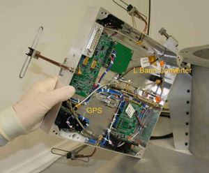
Tray No 5 -The receivers.
This completed tray holds the 70cm linear transponder receiver and two 70cm FM receivers, one for the FM transponder, the other a telemetry receiver for control and command.
This completed system is integrated into the final assembly unit and running "on-air" using external antenna while KiwiSAT sits in its clean environment chamber at ponga Road.
The Attic.
Completed and integrated into the final assembly unit.
Looming Up
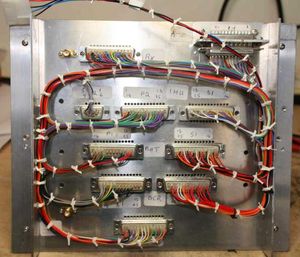
Wiring of the frame, part of the final integration, was completed early and now forms part of the fully integrated KiwiSAT.
Ground Testing
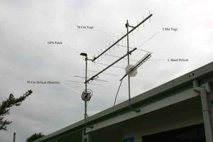
KiwiSAT, in its flight configuration, is in the AMSAT-ZL clean environment chamber at Ponga Road. A remote antenna system allows live testing via the flight mode.
Auckland is reasonably hilly and with the team spread over a wide area, these good antenna are required to guarantee reliable communications.
Solar Panels
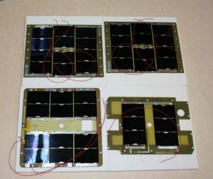
The six flight solar panels are now assembled and tested awaiting final integration. Note the featured picture shows two of the four side panels plus the top and bottom (+Z/-Z) panels, there being the fewest panels on the bottom panel.
AMSAT-ZL Clean Box
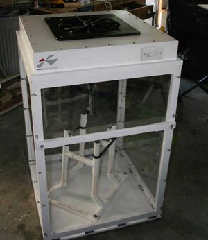
With the construction project now complete and with testing well advanced, the need for a Clean Room has passed. KiwiSAT is now housed in its own Clean Box. This allows for safe transportation, continued testing, and easy demonstration to our important launch sponsors.
AMSAT-ZL appreciate the professional assistance of the Fan and Filter suppliers in the development of the Clean Room at Massey University and the AMSAT-ZL Clean Box.